
In the previous post, Timer 0 as an Internal Counter was explained and configured to use the internal clock (i.e. the oscillator) to count a defined quantity of time. However, the External Counter will consider pulses outside the microcontroller, such as push buttons, sensors, transductors, etc. Likewise the Internal Counter, every time as overflow occurs, an interrupt will handle the emergent situation.
Abstract vector created by macrovector – www.freepik.com
Before reading this, you will need to know how to setup MPLAB IDE and how to connect the PICkit to the PIC microcontroller. If not, check them out first. Check out also another projects for beginners in 8-bit PIC microcontrollers.
Table of Contents
Requirements for Timer 0 as External Counter
Components and Devices
In this tutorial, all the components are Through Hole.
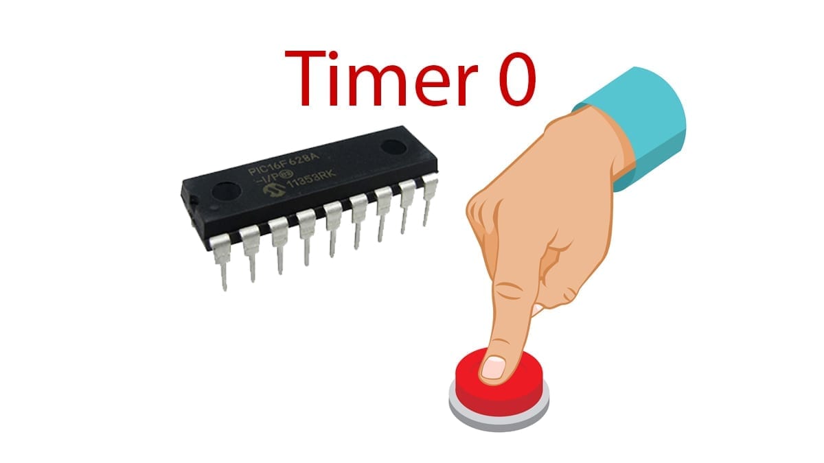
- PIC16F628A: 1 unit.
- LED, any color or size: 1 unit.
- Resistors, 1/2 or 1/4W, 5% tolerance:
- 1KΩ : 1 unit.
- 10KΩ : 1 unit.
- Push button, type SPST: 1 unit.


Check out the commercial values of resistors and capacitors here.
PIC microcontroller
For this tutorial, I will use the 8-bit microcontroller PIC16F628A. This one is the very first one that I learned to program. Very practical too. Be sure to select Through Hole or ‘TH' version. Surface Mounted won't fit in the breadboard.

Download the datasheet here. I recommend that you print in reduced A4 all the datasheet because it will serve you as quick reference.
Tools and Machinery
- Breadboard: 1 unit.
- AC/DC Power Adapter to 5V DC, with at least 500mA: 1 unit.
- Jumper or UTP Wires: various.
- Multimeter: 1 unit.


The Design of the Timer 0 as External Counter
Before reading further, make sure that you read how the Timer 0 works and how it is configured. All the details from the step-by-step guide is detailed here.
To make a practical tutorial, let's count 10 times with a push button. Afterwards, an LED will be turned on briefly and it will be turned off back. For this case, Timer 0 register has to be filled near its limit.
Timer 0 is a 8-bit counter. This means it can count from 0 to 255 (i.e. 2^8). But to make it useful, let's set it from 245. It will count with every press of the push button and there will be a overflow (from 255 to ‘256') after the 10 presses. This way, the Timer 0 flag will be set and the task or command will be executed.
Programming the Timer 0 as External Counter
Configuration Bits
On table 6-1, located in page 47, the registers associated with Timer 0 are displayed. Let's start with the Option Register.

Firstly, in the function config() the registers are configured to match the desired operation. To do so, go to page 23 in the datasheet to read about the ‘Register 4-2: Option Register'. The bit T0CS must be set to 1 in order to count from the external source, which is the RA4 pin. Next, the bit PSA must be set to 0 for the prescaler to work with the Timer 0. The Source Edge bit T0SE let us choose between a high-to-low or low-to-high trigger. If your circuit requires a specific option, then select either 1 or 0, respectively. The final bits PS2:PS0 requires to be 0 because the external clock input RA4 and the prescaler requires to have the same output. Therefore, the prescaler 2 will be 000. Now, this is translated into code:
//Timer 0 configurationT0CS=1;T0SE=1;PSA=0;PS2=0; PS1=0; PS0=0;The value of the TMR0 has to be preloaded in the configuration and everytime an interrupt occurs.
TMR0=245;Afterwards, the Timer 0 enable bit must be set, the flag bit reset and finally the Global Interrupt Enable must be set.
TMR0IF=0;TMR0IE=1;GIE=1; Now, it's configured. But what should it do every time that the overflow occurs? Let's deal with the interrupt.
Interrupt Function
If you haven't read about the Interrupt Sources or how to handle Functions in C, check them out first.
Create the function called void __interrupt(void) interruptFunction(). From this place, all the interrupts are handled. Specify the enable bit and flag bit in order to enter the function. In addition, write the Routine_Tmr0() to specify where it should go next if Timer 0 requires the attention.
//Interrupt Sources if(TMR0IE && TMR0IF) { TMR0IE=0; //Disable Timer 0 interrupt Routine_Tmr0(); TMR0IF=0; //Once attended, erase the interrupt flag from Timer 0 TMR0IE=1; //Enable Timer 0 interrupt }And now, let's attend the interrupt of Timer 0 caused by the overflow. Let's program a small LED blink, the same way it was done in the previous tutorial.
void Routine_Tmr0(){ PORTBbits.RB3=1; //LED On //delay unsigned int x; x=0; while(x<65000) x++; PORTBbits.RB3=0; //LED Off TMR0=245; //Reload the TMR0 value}Extra Coding
On MPLab, select ‘Production' tab from the main menu and then clic ‘Set Configuration bits'. I recommend selecting the internal oscillator for simplicity. Select the following options:
/*------------------------------------------------------------------- 1. DEFINITION OF BITS, PINS, ALIASES, CONSTANTS---------------------------------------------------------------------*/// CONFIG// Oscillator Selection bits (INTOSC oscillator: I/O function on RA6/OSC2/CLKOUT pin, I/O function on RA7/OSC1/CLKIN)// Watchdog Timer Enable bit (WDT disabled)// Power-up Timer Enable bit (PWRT disabled)// RA5/MCLR/VPP Pin Function Select bit (RA5/MCLR/VPP pin function is digital input, MCLR internally tied to VDD)// Brown-out Detect Enable bit (BOD enabled)// Low-Voltage Programming Enable bit (RB4/PGM pin has PGM function, low-voltage programming enabled)// Data EE Memory Code Protection bit (Data memory code protection off)// Flash Program Memory Code Protection bit (Code protection off)// #pragma config statements should precede project file includes.// Use project enums instead of #define for ON and OFF.In the config() put the pin configuration (1 for everything except for RB3).
//Pin ConfigurationTRISA = 0b1111111; //RA7 to RA0.TRISB = 0b11110111; //RB7 to RB0.PORTA=0; //Clean PORTAPORTB=0; //Clean PORTBDon't forget to add the While(1) in the Main function to make it run forever!
while(1) {}Download the code of Timer 0 as External Counter
If you would like to see and read the whole code through, enter your name and e-mail in the form below to download the project. I promise that I won’t send you spam; just relevant content to the blog. If you don’t see any form below, please click here.
Schematic of Timer 0 as External Counter
For reference, here is the schematic used.

Picture of Timer 0 as External Counter
This is how the Timer 0 looks like in the breadboard.

Testing the Timer 0 as External Counter
Finally, a video testifying that it can count until 10. For a short time, a LED is lighten up.
Conclusion
This post has explain how to use Timer 0 to count from external pulses. The code has been written and it's downloadable! The schematic, foto and video has been recorded to show how it is done.
Did you noticed that the counter not always counts exactly 10? It's an inherent problem with push buttons called Switch Bounce or Contact Bounce that can be dealt with hardware or software. More about that in a future tutorial.
Check out two other tutorials about timers: Timer 1 and Multiplexing. The links will be linked here for you when there are written.
Further reading
To read more about the beginner's guide to 8-bit PIC microcontrollers, refer to the following posts:
 How to drive 7-Segment Displays with a 8-bit PIC - Learn how to drive 7-segment displays using the PIC16F684 microcontroller. Download the code and watch an example. Click here to…
  Multiplexing Traffic Lights easily in a PIC microcontroller - Using the 8-bit PIC16F684, a circuit for multiplexing traffic lights is assembled in a breadboard with simple LEDs. Click here…
  Timer 1, how to make a reliable Real Time Clock in 8-bit PIC - In this tutorial, a Real Time Clock RTC is done using Timer 1 and the 32768Hz oscillator in a PIC…
  Timer 0 as External Counter in 8-bit PIC microcontroller - Timer 0 can also be set as external counter. This way it can act upon reaching a certain threshold. Click…
  Timer 0, a simple Counter in 8-bit PIC you need to know - Timer 0 is a counter that is always working and it's used commonly to refresh information on screens. Click here…
  Interrupt sources in 8-bit PIC and how to quickly attend them - Interrupts are the critical way to manage emergent situations in a PIC microcontroller. Click here to read to learn the…
  Code Template, an easy guide for PIC Microcontrollers in C - Writing a program with order is a time saver. Download today the code template for PIC microcontrollers for free. Click…
  Blinking LED with a PIC microcontroller, a helpful Indicator - Learn how to continuously turn on and off a simple LED; in other words, to blink a LED. The microcontroller…
  Hello World with 8-bit PIC microcontroller - Hello World is the first code in any programming language and now it's applied to a PIC microcontroller. Click here…
  How to connect any PICkit to a microcontroller - PICkits are the tools for programming PIC microcontrollers. Do you want to learn how to connect a PICkit? Click here…
 You have reached this far!
Thank you for reading the blog post. Your comments and suggestions are welcomed. At the bottom of this page, leave a message or just say hi! The whole team of techZorro will appreciate it. Don't forget to share it on social media as well.
techZorro’s Index of Content
Click on the following link to browse likewise content in the blog in techZorro. This index will help you see what you are looking for in a bird’s eye view.
techZorro's Newsletter!
If you enjoyed this blog post, please subscribe to techZorro’s newsletter so you don’t miss any future blog posts!
techZorro's Index of Content
Keep Reading!
- 008 – Variable Frequency Drives: how this controller can transform induction motors forever
 AC induction motors can be transformed into a highly controllable machine with Variable Frequency Drives or VFD. Click here to listen.
 - 006 – Regenerative Braking, an awesome Feature found in Electric MotorsThis episode is related to this hidden feature of electric motors called regenerative braking. Click here to listen.
- 005 – 7 types of Electric Motors that you should know aboutThere are several types of electric motors that differs in efficiency, power, cost, torque output, etc. Click here to listen.
- 004 – AC Voltages, Frequencies and Plugs around the WorldLet's talk about electricity! Specifically about how the standards around the world. Click here to listen.
- 002 – RISC vs CISC, how a few Differences are crucial to ComputingToday in the market is found two kinds of processor architectures: RISC and CISC. Both have some advantages. Click here to listen.


