
Learn how to continuously turn on and off a simple LED; in other words, to blink a LED. The microcontroller used here is the PIC16F628A and you are going to use variables. A blinking LED can be used effectively as an indicator and in some cases as communication interface.
In a previous post called Hello World, a LED was simply turned on. This post is about blinking the LED (turn it on and off repeatedly), so the novelty here comes in software.
Before reading this, you will need to know how to setup MPLAB IDE and how to connect the PICkit to the microcontroller. If not, check them out first. Check out also another projects for beginners in 8-bit PIC microcontrollers.
Table of Contents
Requirements for Blinking LED
Components and Devices
In this tutorial, all the components are Through Hole.
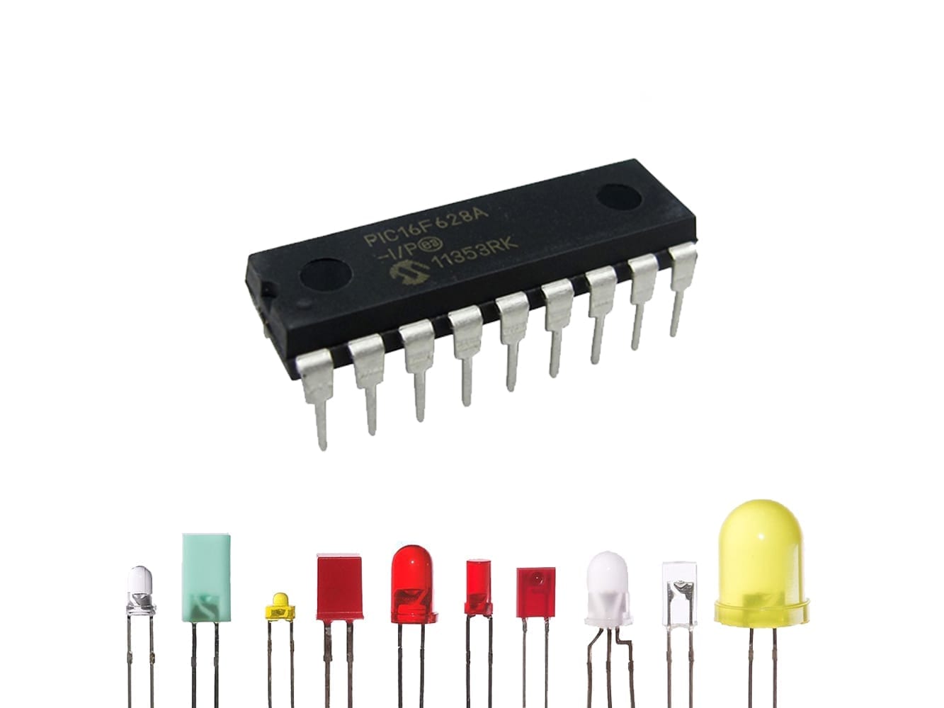
- PIC16F628A: 1 unit.
- LED, any size or color: 1 unit.
- Resistors:
- 330Ω, 1/2 or 1/4W: 1 unit.


Tools and Machinery
- Breadboard: 1 unit.
- PICkit (3 or 4): 1 unit.
- AC/DC Power Adapter to 5V DC, with at least 500mA: 1 unit.
- Jumper or UTP Wires: various.


Schematics for Blinking LED
Schematic
A simple LED with the resistor is needed for this circuit. Just connect them to the pin RB3 as shown below. Use the same 330Ω resistor as the previous Hello World post.


Photo
A picture of the circuit was taken as reference.

Code for Blinking LED
Configuration() function
Just like the previous tutorial, we have to set the Configuration Bits. The exact code can be found below.
- Turn off:
- The internal oscillator (FOSC) running at 4MHz.
- Watchdog Timer (WDT).
- Master Clear (MCLR).
- Turn on:
- Power-Up Timer (PWRTE)
- Brown-out Timer (BOREN).
The rest is unimportant for now.
Above main(), open a new function called config() and paste the following code:
config(){ // CONFIG // Oscillator Selection bits (INTOSC oscillator: I/O function on RA6/OSC2/CLKOUT pin, I/O function on RA7/OSC1/CLKIN) // Watchdog Timer Enable bit (WDT disabled) // Power-up Timer Enable bit (PWRT enabled) // RA5/MCLR/VPP Pin Function Select bit (RA5/MCLR/VPP pin function is MCLR) // Brown-out Detect Enable bit (BOD enabled) // Low-Voltage Programming Enable bit (RB4/PGM pin has digital I/O function, HV on MCLR must be used for programming) // Data EE Memory Code Protection bit (Data memory code protection off) // Flash Program Memory Code Protection bit (Code protection off) //More code comes after this line}Pinout Configuration
All PORTA is unused, therefore let's leave it as input (because it has higher impedance). Just the RB3 from PORTB is going to be used as output, therefore
TRISA=0b11111111; //They are unused, therefor leave them with '1'.TRISB=0b11110111; //Only RB3 will be an output (therefore the '0'). Leave the rest of 1.PORTA=0; //Clean the ports.PORTB=0;Run it forever
After adding the configuration bits, remember to add the while to run the program forever.
while(1) {}Creating delay
Let's write some code that freezes the microcontroller temporally.
WHAT??!! Why would anybody want to make it STOP for a while? It is actually more useful than you might think.
For this tutorial specifically, we will need it to make the LEDs perceptible to the human eye. In fact, you don't freeze it, you just make the microcontroller to idle or do nothing for a small period of time.
Definition
There are many ways to make a processor to do nothing for a while. One of them is to make it count for a determined amount of time.
Declare the local variable x as integer.
int x;Remember that integer can store values from -32,768 to 32,767. Let's make it count different values and let's find out empirically how many time in seconds this happens to be. Try for example: 100, 1000, 10000 and 32000. Let the program count from 0 to the values previously specified using while and x++.
x=0;while(x<10000) x++;When I tried out the 10000 value, the Blinking LED was turning on and off for about 3 times per second.
Blinking the LED
Now, you just have to give the command to turn the LED on:
PORTBbits.RB3=1; //LED Onand then turn the LED off:
PORTBbits.RB3=0; //LED OffDownload the code of the Blinking LED
If you would like to see and read the whole code through, enter your name and e-mail in the form below to download the project. I promise that I won't send you spam; just relevant content to the blog. If you don't see any form below, please click here.
Testing the Blinking LEDs
If you don't know how to compile and code a project into a PIC microcontroller, follow this link to my tutorial.
If everything executed properly, you should see a message in the bottom of the Output window confirming that the programming process has been complete.
Next Chapter
The next series of posts will be related to transistor switching. Subscribe to the newsletter if you haven't already so you don't miss out!
You have reached this far!
Thank you for reading the blog post. Your comments and suggestions are welcomed. At the bottom of this page, leave a message or just say hi! The whole team of techZorro will appreciate it. Don't forget to share it on social media as well.
techZorro’s Index of Content
Click on the following link to browse likewise content in the blog in techZorro. This index will help you see what you are looking for in a bird’s eye view.
techZorro's Newsletter!
If you enjoyed this blog post, please subscribe to techZorro’s newsletter so you don’t miss any future blog posts!
techZorro's Index of Content
Keep Reading!
- 008 – Variable Frequency Drives: how this controller can transform induction motors forever
 AC induction motors can be transformed into a highly controllable machine with Variable Frequency Drives or VFD. Click here to listen.
 - 006 – Regenerative Braking, an awesome Feature found in Electric MotorsThis episode is related to this hidden feature of electric motors called regenerative braking. Click here to listen.
- 005 – 7 types of Electric Motors that you should know aboutThere are several types of electric motors that differs in efficiency, power, cost, torque output, etc. Click here to listen.
- 004 – AC Voltages, Frequencies and Plugs around the WorldLet's talk about electricity! Specifically about how the standards around the world. Click here to listen.
- 002 – RISC vs CISC, how a few Differences are crucial to ComputingToday in the market is found two kinds of processor architectures: RISC and CISC. Both have some advantages. Click here to listen.
[…] You can see other examples of unorganized code in this post “Blinking LED with a PIC microcontroller, a helpful Indicator“. […]
Your C Code is full of NULL characters. every part of the proyect is NULL. Please re-upload or check your compresed “zip
Hey K. Thanks for the reply and observation. I will check it this week out and hopefully upload it right away.